Columbia was different to all the other orbiters because it had a SILTS (Shuttle Infrared Leeside Temperature Sensing) pod added to the top of the tail. This was used a number of times to measure the temperatures being experienced by the orbiter during re-entry.
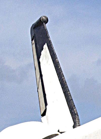
I’ve been told that other shuttles also had the SILTS pod, and seen some model builds of other shuttles that feature it but to the best of the research I’ve done Columbia was the only one to have this. For example, the picture below is of the fin of Atlantis, where as far as I can find out no camera was ever fitted. These pictures also show one of the problems with doing an accurate representation of a shuttle. The pattern of tiles varies between them all, just look at the black tiles around the top of the fin on Columbia for example. Many more examples will no doubt follow.
Atlantis
The picture on the right shows the SILTS camera fitted to Columbia. This was taken as the orbiter was moved to the vehicle assembly building (VAB) in preparation for mission STS-107.
Columbia
Fitting of the SLITS pod is a simple affair. The kit parts were marked up using the resin parts as a template. The tip of the fin was then cut off.
Marked up
And the resin part was glued on following a little bit of sanding and fitting.
New Part
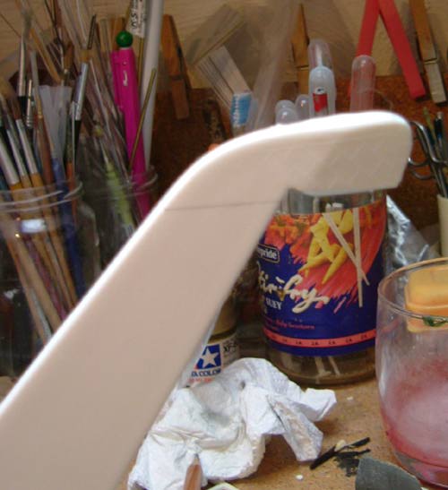
Although there is still some sanding and shaping required the SILTS pod now sits on the top of the tailfin.
Primed
There is also a need to add a parachute to the bottom of the tail area, which were fitted during the lifetime of the shuttles. You can see this area quite clearly in this picture taken during the rollover of Columbia to the vehicle assembly building for flight STS-107. It is the area at the bottom which has black tiles on the lower surface. This will be done by cutting a section out of the kit parts and rebuilding it with plastic sheet.
Parachute
I found (sorry I can’t remember where now as too much time has elapsed) this very useful diagram of the parachute area and what is needed to make it more accurate.
Chute Diagram
So started by marking up the line where the piece would be cut out.
Marked up
And with that part removed.
Removed
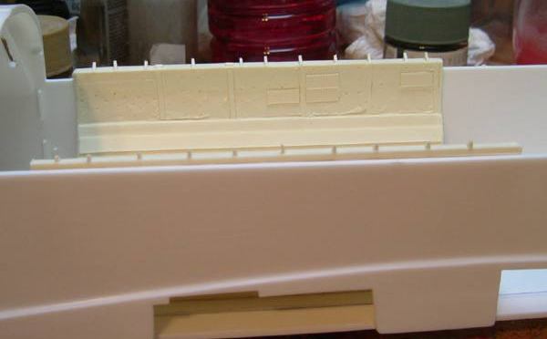
And then built up the underside part according to the diagram above.
Built Up
Finally a fine cut was made into the control surface where it meets the tail at the top and bottom to give a small gap and show that this is a separate part.
That brings the tail to the right shape.
Unfortunately this part suffered when we moved house and got broken off. Should be a relatively easy fix with luck as doesn’t look like anything has been distorted out of shape.
As mentioned previously the cargo bay will be very visible in this model. The Real Space cargo bay set is excellent but does present some problems. The major on is that it is designed for the Monogram kit which is apparently different in some dimensions and it requires some manipulation and cutting to get it to fit.
The first problem was the depth of the cargo bay compared to the resin parts. Simply there isn’t enough space for them to drop neatly into the space available. As you can from the picture they project quite a bit over the top.
Too Tall
My solution to this problem was to cut the floor out of the kit parts which would allow the parts to sit lower. I marked up the cuts by looking through the open end where the engines will go.
Floor marked up
This areas was then cut out with a cutting blade in my Dremel-a-like drill.
Floor Removed
And as you can see the parts now sit down far enough.
Aligned
The second different between the Revell and Monogram kits is that the cargobay of the Monogram version must be about 5mm longer, because the resin parts are too long. It’s fortunate it is this way round as it’s much easier to remove a bit than try to build it up. So working extremely carefully I cut the required amount off the front end of the cargobay. And as you can see it now fits fine.
In PlaceIn Place
And with a couple of coats of white primer. There are still some areas which need to be filled between the bay bottom and the end walls.
The cockpit is not really greatly visible once the kit is assembled but some aspects can be seen through the windows, so I didn’t want to leave this bare, but to make it as detailed as possible, without spending a huge amount of time on it. Unfortunately this second part didn’t work out as I ended up spending a disproportionate amount of time on it, without an end result which justified the time invested.
The first thing I did was to assemble according to the instructions. But one obvious part that is lacking are vertical partitions which are clearly visible just behind the windows. These parts are visible in this reference picture as the broad panels which I have marked.
The Real Thing
This was replicated with two small pieces of plastic between the front and real cockpit parts. there was a gap between these parts anyway, so this acted as a filler as well.
Cockpit
In addition there was a large gap between the cockpit and the main body when I test fitted it, so I extended the cockpit’s front edge out slightly with some plastic and some car body filler (which is the pink parts).
Cockpit
I also opened up the hatch which goes down to the mid deck which can just be seen on the left in this particular picture (although I don’t think it will be seen once it’s assembled).
Cockpit
At this point I ran into a number of problems, some of my own making. Firstly I had a reaction between two different paint types. I had originally painted the entire cockpit with a Tamiya acrylic. I wasn’t entirely happy with the colour, which is shown on the right, and decided to go for a ghost grey. The only ghost grey I had was a Testors Modelmaster Acryl so I used that. The two reacted against each other a resulted in a lovely crinkly effect, so it was back to the drawing board for that. The cockpit was stripped with Mr Muscle oven cleaner and rubbed down with some fine sandpaper.
Secondly because I am now using the Real Space cargo section, which is far more detailed and accurate, I can’t use the back piece for the cockpit from the kit. This has resulted in a lot of fiddling around trying to work out the best way to fit the cockpit. It is finally shown in place in the picture, reprimed in white.
In position
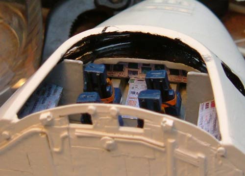
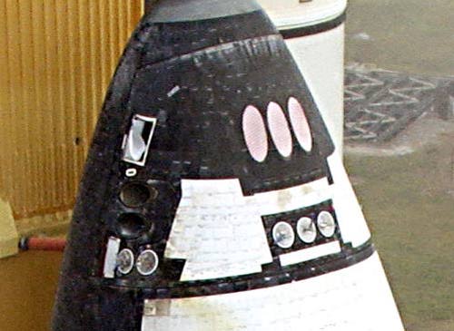
The control panels on Columbia had just been upgraded to the MEDS (Multifunction Electronic Display System) and the panels are reasonably visible from the outside. I decided to try and replicate them by printing them out and sticking them into place within the cockpit. The graphic to the right shows these panels. There are two main display panels. The one at the top is the original type and the one at the very bottom is the new MEDS display. Also scattered around are some flight manuals and as you can see from the picture at the top the cockpit is covered in blue squares. I believe these are velcro so things can be put down without floating away.
Console Graphics
And here are the console graphics in place. The do an adequate job of showing the detail, although of course they aren’t 3-dimensional.
In Place
You can just about make out the MEDS display in this picture, and if you squint through the rear windows you can just see it.
In Place
The seats have also been reworked. The headrests were cut off and reattached on two plastic rods. A Milliput headrest was built up as was the back cushion (the orange part). The seatbelts are made from paper strip, but they don’t lay properly so I will probably redo them with the top off a wine bottle.
The Forward Reaction Control System (RCS) controls many aspects of the shuttles flight while in orbit. While on the ground there are covers over these thrusters to stop foreign objects falling in and potentially damaging the motors. In orbit the are open. The model has most of them moulded as if the covers are in place. Particularly the ones on the side.
The picture shows the shuttle out at the launch pad and it still has the covers. Pictures without the covers in place are not common since it’s presumably difficult to take pictures of them while in orbit.
RCS Thrusters
This shows the details on the kit, with the flat, featureless areas where the thrusters should be. If this was a model of the shuttle stacked up then these would be fine with a little extra detailing.
RCS Thrusters
They were drilled out and the area smoothed off with needle files and sandpaper.
RCS Thrusters
The holes were backed with a big squash of Milliput and working slowly with the tip of a paintbrush the thruster bells were formed in the soft Milliput. Using water and a little alcohol you can produce a vert good finish. Also allow the Milliput to set up for a few hours before giving it a final polish while still slightly soft.
RCS Thrusters
The thrusters on the nose were more detailed than those on the side but the oval ones at the front still looked too flat, so these were also removed.
Top RCS
Here they have been drilled out.
Top RCS
And filled in using the same Milliput technique described above.
The starting point for the build is the long list of items I’ve purchased to complete it in the way I have in my mind.
The Revell Space Shuttle
I have elected to do this in 1:72 scale, which is the largest commerically available version of the Shuttle. The choice is the Revell version or the Monogram version, both companies having produced their own versions prior to them merging. The Revell version was the only one I could get hold of so this limited my choice and decided on the model. I found mine at Hannants and didn’t really realise what I was letting myself in for until it arrived. This is a big model and is going to take some time and a great deal of effort to build. In retrospect maybe using a 1:144 model would have been a better bet, but it should certainly be impressive once it’s finished.
The first clue that this was going to be a major project was the size of the box. This thing is huge.
The Box
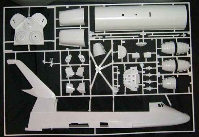
The first sprue which has the left hand side of the fuselage, the cargo bay doors and some of the smaller parts including the two astronaut figures.
Parts
Revell have made an attempt at representing the thermal tiles and blankets which protect the shuttle by adding raised panel lines. You can just about see them in this picture. These will need to be sanded off.
Panels
The second sprue with the underside and the ends of the cargo bays. Also parts of the landing gear which wont be used in this build.
Parts
The underside has a finely etched tiles pattern on it which will need to be filled into order to use the tile decals.
Raised Tile Details
The topsides of the wings and more of the landing gear parts.
Parts
The right hand side of the fuselage, the interior of the cargo bay and the engine bells.
Parts
The interior parts for the cargo bay. These will probably not be used as the contents of the cargo bay change from mission to mission and these elements were not present on Columbia on STS-107. The access tunnel (the parts on the left in the middle) might be useable with modification.
Parts
Finally the clear parts.
Parts
Decals
Columbia was the first of the shuttles put into active service but the markings were updated during her lifetime and included the NASA meatball rather than the worm logo. Those supplied by Revell represent the original ones, so replacements would need to be sought.
The Revell decals only contain the original NASA logo used, which is known as the worm logo (that curvy NASA text). I realised in advance that the decals supplied with the kit would not be sufficient to allow a modern Columbia to be built.
Revell Decals
There are a couple of choices for replacement decals. Meteor Productions did a set under their Cutting Edge Decals banner (now defunct and not available anymore) and a set is also produced by Real Space Models. Each has it’s pluses and minuses but either will produce a much better end result. I opted for the Cutting Edge’s decals based on other items I wanted and the ease of ordering them in one go.
The replacement decals from Cutting Edge contain all variants on the styles used by NASA on shuttles upto the current time.
Cutting Edge Decals
The current meatball logo is the large blue one. Three different decals are also provided for the access hatch and all the different names and sizes.
Cutting Edge Decals
Thermal Tiles
One of the most obvious features of the shuttle are the hundreds of thermal tiles which offer protection from the extreme heat of re-entry. The Revell model offers a half-hearted attempt to represent these with a few raised lines. This is really not the effect I was looking for and instead I opted to purchase (although they are expensive) a set of Cutting Edge Decal’s. These consist of three A4 sheets of decals which allegedly are an exact match to the colour of the tiles actually applied.
As you can see these are a major set of decals which will no doubt test the skills of any model builder.
Cutting Edge Tile Decals
The right hand side of the wing underside.
Cutting Edge Tile Decals
The majority of the white tiles.
Cutting Edge Tile Decals
The left hand side of the wing underside together with the nose areas.
Tile Decals
Painting Masks
Having invested in the above decals I spent another few dollars and bought the Black Magic painting masks. These are a set of precut vinyl masks which can be applied to the model so that the time spent masking and painting can be dramatically reduced. Like the logos the painting pattern of the shuttle varies from orbiter to orbiter and also with time. The masks are an attempt to cover all options. After all this time I don’t know if they will still work but I can at least use them as a template.
Obviously there is no scan of the parts as they are a black sheet, this is the key to allow you to identify what parts you will need.
Vinyl Masks
SILTS Camera
One further modication which was made to Columbia during her service life was to install a Shuttle Infrared Leeside Temperature Sensing (SILTS) instrument on the top of the tailfin. I believe that this was unique to Columbia and was not included on any other orbiter. Cutting Edge come to the rescue again with a small resin part to represent the SILTS Camera.
SILTS
Engine Nozzles
I had anticipated that that would be the extent of the aftermarket parts I would use, but I noticed one final thing and decided to add it to the shopping basket. Namely a set of replacement engine nozzles. Having built a few Ma.K. models with engine nozzles I know that these are generally supplied in two parts and it is difficult and frastrating trying to get the seams to vanish and often you end up with flat surfaces where they have been sanded. In addition I found out that the parts supplied with the Revell kit are inaccurate as well.
The Cutting Edge replacement engine nozzles. They are single pieces and have correct details on them.
Resin Engines
A comparison to the Revell parts. The lack of a seam on these replacement parts probably makes them worth it in their own right. Joining two part nozzles is extremely difficult.
Engines
The real thing at Launch Complex 39 at the Kennedy Space Center. Fortunately replicating all that piping wont be necessary.
Shuttle Engine
Cargo Bay
This is something of a postscript. Once I had all the parts to hand and started thinking more carefully about the build I realised that the cargo bay would be one of the most visible areas, since this was to be an in-orbit version of the shuttle. The cargo bay that comes with the kit is sparse and not very detailed. A lot of detailing would probably make it OK but there was an alternative in the form of the Real Space Models cargo bay set. This set is excellent and the level of detail is really quite amazing. But it is designed for the Monogram Space Shuttle which was to introduce some difficulties.
The cargo bay area comes in two parts which must be carefully glued together.
Cargo Bay
Another view. These parts are extremely well detailed, with all the thermal blankets nicely rendered.
Cargo Bay
The ends of the cargo bay are also supplied to replace the kit parts.
Cargo Bay
You also get a set of photoetched brass parts which will form the details like the grab rails and the cargo bay door hinges, a large stainless steel photoetched sheet for the radiators and a number of small resin pieces for the antenna, cameras and robot arm. I wont be using the arm for this build since it wasn’t fitted to Columbia for this mission.
Cargo Bay
A close up of the resin parts.
Cargo Bay
And a close up of the photoetched sheet.
Photo Etch
That just about wraps up where I was starting from. The next step is to start some of the modifications which are required and sand off the raised lines of the kit.